
Electrical Wiring Guide for Admiral Hub and Lock
There are two ways to connect your Admiral Hub or Lock to trailer power. We recommend using the supplied power tap harness, which connects directly to the trailer’s existing wiring without cutting or splicing wires.
Method 1: Supplied Power Tap Harness (Recommended)
The power tap harness connects inline with the trailer’s existing 5-pin power connection, typically located near the rear axles or ABS controller.
It provides two power outputs: one for the Admiral Hub and another for the optional Admiral Lock.
Installation steps
- Locate and disconnect. With trailer power disconnected, locate the existing 5-pin power connection and unplug it.
- Connect the harness. Insert the power tap harness between the two disconnected connectors. Connect port 2 to the trailer side and port 3 to the power cable leading to the ABS ECU.
- Connect your devices. Plug the Admiral Hub into either two-pin output. Connect the Admiral Lock to the second output if required.
- Verify operation. Restore trailer power and confirm that the devices receive power and the trailer ABS system operates normally.
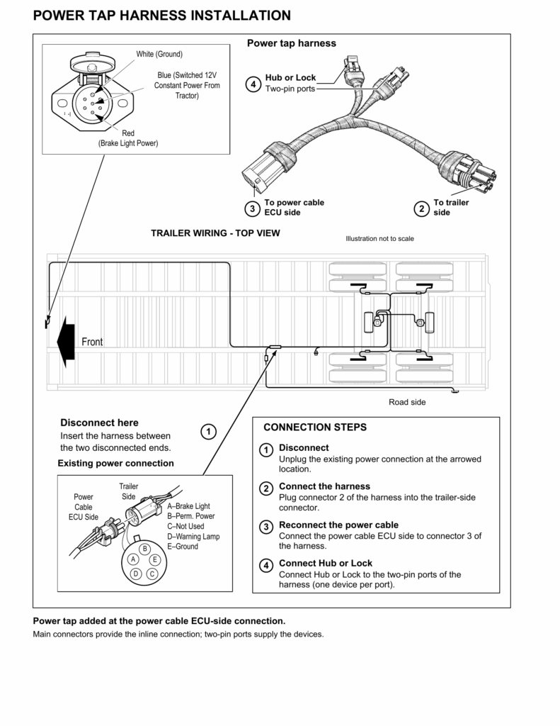
The harness preserves the original power connection while providing two additional outputs for Admiral devices.
Important: Confirm that the harness is compatible with your trailer’s connector and electrical system. Ensure the required circuit protection is present.
Method 2: Custom Electrical Wiring (Alternative)
If you prefer to use your own wiring harness, follow the electrical requirements and connector diagrams below.
Power Requirements
The Admiral Hub requires a fused 12V DC power supply to operate and recharge its internal battery. The Admiral Lock can optionally use external power; otherwise, it operates on its internal battery.
Both devices are designed for 12V operation, with an approximate average current draw of 500mA per device.
- Fuse protection: A suitable fuse is mandatory for the power supply to both devices.
- 24V systems: Use a 24V-to-12V DC converter. Never connect 24V directly to the Admiral Hub or Lock.
- Ignition-switched power: When using the Hub with an immobilizer, its external power supply must be ignition-switched. Do not connect it directly to a permanent battery source.
- Connector selection: Do not use an unswitched permanent-power connection for the Hub when immobilization is enabled.
Always consult the official wiring diagram for your trailer or tractor. Verify voltage, polarity, and switching behavior before connecting equipment.
Electrical Connector Reference Diagrams
The following diagrams illustrate the standard electrical interfaces used in trailer installations.
Warning: Always refer to the official wiring diagram for your specific trailer, power unit, or tractor equipment before beginning any installation. Electrical systems may vary, and incorrect connections can cause damage or inhibit system functionality.
Important: The power supply line must have a fuse installed to protect against electrical faults. This is mandatory for both the Admiral Hub and the Admiral Lock.
The Admiral Hub requires a 12V DC power supply for operations and to recharge its internal battery. The Admiral Lock can optionally be powered externally; if not connected to a power source, it will operate on its internal battery. Both devices are optimized for 12V systems and have an average current draw of approximately 500mA.
For installations on 24V systems, a 24V-to-12V down converter must be used to supply appropriate voltage levels to the Admiral Hub and Lock. Using 24V directly without a converter will damage the units.
When integrating the Hub with an immobilizer, it is critical that the power supply is switched via the vehicle’s ignition. This ensures that immobilization functions properly when the asset is parked and prevents inadvertent unlocking. Refer to the included wiring diagrams for proper ignition-switched connections.
Do not connect the Hub to a permanent battery source, as this will disable the immobilization function when the vehicle is parked and turned off.
SAE J650 (12V)
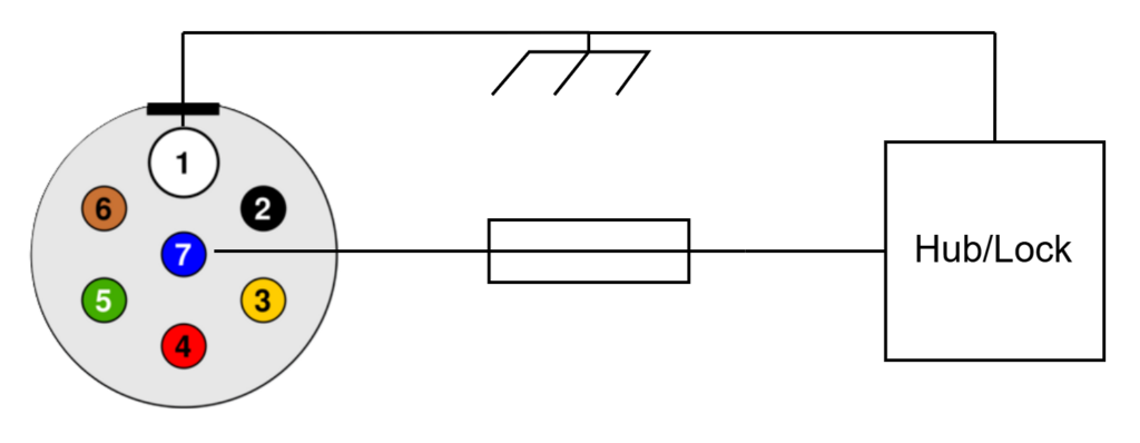
ISO 1185 (24V)
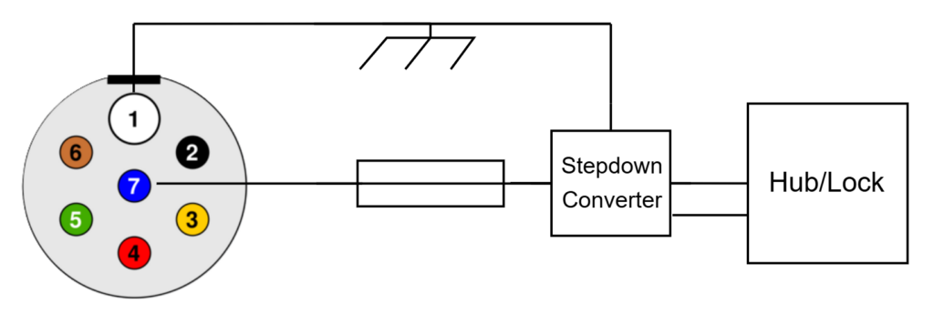
ISO 7638-2 (12V)
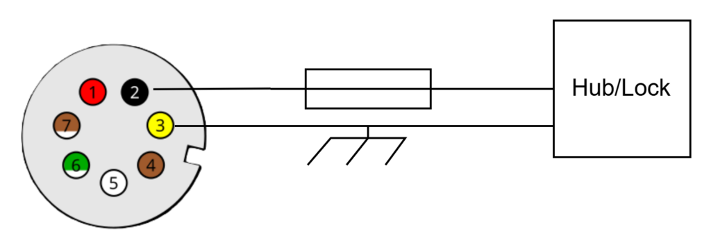
ISO 7638-1 (24V)
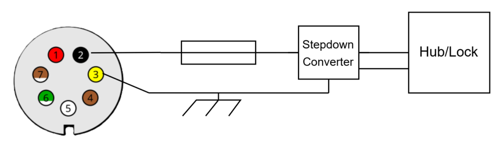
ISO 3731 (24V)
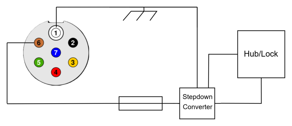
Important: Connector types, wiring assignments, and available power supplies vary by trailer. Confirm the actual circuit before making connections. Incorrect wiring can damage equipment or interfere with trailer safety systems.